How machine rigidity affects machining accuracy is not an abstract engineering question. It appears directly on the shop floor, where a thin aluminum wall vibrates, a tool leaves visible chatter marks, and a finished bore misses its target.
Tony Schmitz, a leading researcher in machining dynamics, describes the problem clearly: “Chatter is a self-excited vibration.” That vibration often grows when the machine structure, workholding system, or tool assembly lacks sufficient stiffness. A rigid setup resists cutting forces more effectively. It limits deflection and helps the tool follow its programmed path. The result is usually better dimensional accuracy, surface finish, and process stability.
Small movements matter. A cutting force of only a few hundred newtons can bend a long tool or shift a flexible fixture. The effect may be measured in microns, yet those microns can ruin a precision bore or prevent two components from fitting. Rigidity also influences tool life because unstable contact creates uneven loading and sudden edge damage.
This article examines how machine rigidity affects machining accuracy through practical mechanisms, measurable symptoms, and control methods. It considers spindle stiffness, guideways, fixturing, tool overhang, and workpiece geometry. The analysis should not pretend that rigidity solves everything. Thermal growth, tool wear, programming errors, and material variation still create uncertainty. That is easy to overlook.
A useful evaluation begins with evidence: cutting-force data, vibration signals, surface inspection, and dimensional records. Guessing can help briefly. Measurement is safer. Even experienced machinists sometimes blame the tool first, when the real weakness sits beneath the workpiece.
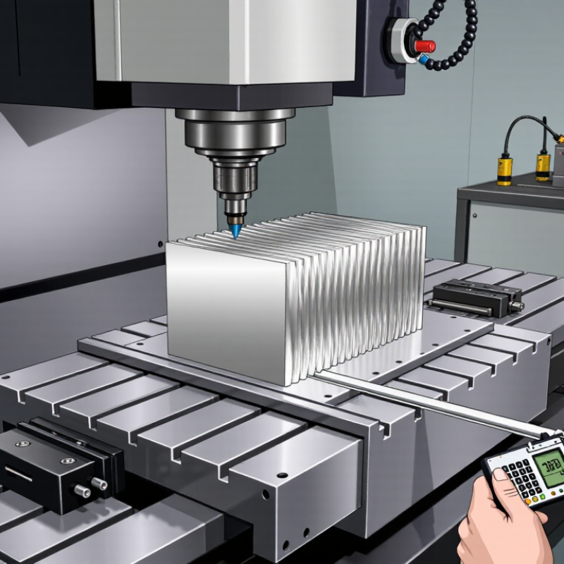
Machine rigidity in machining is the ability to resist deformation under cutting forces. A rigid machine keeps its structure stable while the tool removes material. This stability depends on the bed, spindle, guides, fixtures, and workholding system.
When rigidity is low, cutting forces can bend the tool or shift the workpiece slightly. Even a small movement may create chatter, poor surface finish, and inaccurate dimensions.
For example, a thin plate can vibrate when clamped weakly. A long tool may also deflect during a deep cut. These changes often appear as tapered walls, uneven slots, or unexpected tool marks.
Heat can make the situation worse. However, rigidity alone does not guarantee accuracy. Tool condition, machine calibration, cutting parameters, and operator judgment also matter. Real workshops are less perfect than textbooks suggest.
Tips: Use the shortest practical tool overhang. Tighten workholding evenly and support thin sections carefully. Reduce cutting depth when vibration appears. Check dimensional accuracy at several points, not just one location. Listening to the cutting sound can reveal instability, but sound is not a measurement. Confirm it with inspection tools. I have found that small setup changes sometimes improve accuracy more than expensive adjustments. Still, this result is not universal. Each material and machine responds differently.
Machine rigidity directly affects machining accuracy because cutting force creates elastic deflection. The key variable is stiffness within the complete structural loop: spindle, bearings, column, table, fixture, tool, and workpiece. A 10 kN cutting load acting on a 100 MN/m structure can produce about 0.10 mm of deflection. That error appears on the part immediately.
Joint quality matters as much as casting thickness. Bolted interfaces, guideways, and bearing seats can introduce micro-movement when preload is uneven. Shorter force paths usually improve rigidity. Larger cross-sections help, but excessive mass alone does not guarantee accuracy. Tool overhang is another practical weakness. Doubling overhang can increase tool deflection by roughly eight times under similar conditions. It is easy to overlook this during setup.
Vibration resistance also depends on natural frequency and damping. Poor rigidity can trigger chatter, leaving visible waviness and unstable dimensions. A CIRP Annals review reported that thermal effects may contribute 40–70% of total machining error in machine tools, so rigidity cannot be evaluated separately from heat control (CIRP, 2012). ISO 230-2 and ISO 230-3 provide recognized methods for checking positioning accuracy and thermal behavior. In practice, however, test results may change after warm-up, fixture replacement, or heavy cutting. That is the uncomfortable part. A machine can pass a factory test yet lose accuracy on the shop floor.
The chart shows the calculated tool-point deflection under a constant 1,000 N cutting force. Deflection is determined by the relationship δ = F / k, where F is cutting force and k is machine-tool stiffness. Higher stiffness reduces elastic displacement and generally improves dimensional accuracy, surface finish, and process stability.
Values are engineering calculations based on linear static stiffness; actual results also depend on column and bed design, spindle and tool-holder interfaces, workholding, tool overhang, cutting direction, joints, and structural damping.
Machine rigidity directly controls how cutting forces become tool deflection. During milling, the cutter pushes against the workpiece with changing force. A flexible machine structure bends slightly under that load. Even a small movement can leave visible marks or alter a critical dimension.
Rigidity comes from the machine frame, spindle, fixtures, tool holder, and workpiece connection. Every part matters. For example, a long tool may deflect several hundredths of a millimeter during a heavy side cut. The result can be an undersized pocket, tapered wall, or uneven surface finish. In practice, reducing tool overhang often improves accuracy more than simply lowering feed rate. Shorter is usually better.
Cutting conditions must match the machine’s actual stiffness. High depth of cut increases radial force, while a worn tool can raise force unexpectedly. I have seen operators blame positioning errors when the real problem was fixture movement. That mistake is easy to repeat. Checking tool runout, clamping pressure, and vibration can reveal the cause. A simple test cut also helps: measure the first pass, then compare it with the final pass. If the dimension changes as material removal increases, force-induced deflection deserves attention. Not every vibration has the same source. Sometimes the machine is rigid enough, but the setup is not.
How Machine Rigidity Affects Machining Accuracy?
Machine rigidity directly affects machining accuracy and surface quality. A rigid structure resists bending when cutting forces change. This helps the tool follow its programmed path. Even tiny deflections can create dimensional errors, tapered walls, and uneven edges. Chatter marks may also appear as repeated waves on the machined surface.
In practical machining, rigidity depends on the machine frame, workholding, tool projection, and cutting conditions. A stiff setup usually produces more consistent dimensions and lower surface roughness. However, rigidity alone cannot guarantee a perfect result. Poor alignment, a damaged tool, or excessive feed can still reduce accuracy. I have seen stable machines produce rough finishes because the tool extended too far. That mistake is easy to overlook. Material behavior also matters, especially during interrupted cuts or thin-wall work. Some settings require testing rather than assumptions.
Tips: Keep tool overhang as short as practical. Secure the workpiece with firm, even clamping. Check runout before precision operations. Use dial indicators to verify alignment. Reduce cutting force when chatter begins. Inspect the finished surface under consistent lighting. Record successful settings, but review them when material or geometry changes. A setup that worked yesterday may not suit today’s part.
| Machine Rigidity Level | Approximate Structural Stiffness | Static Deflection Under 1 kN Cutting Force | Typical Dimensional Deviation | Typical Surface Roughness, Ra | Common Machining Effects |
|---|---|---|---|---|---|
| High Rigidity | Approximately 100–250 N/µm | 4–10 µm | Approximately ±5–15 µm | 0.4–1.6 µm | Stable cutting, low vibration, consistent dimensions, and good form retention. |
| Medium Rigidity | Approximately 40–100 N/µm | 10–25 µm | Approximately ±15–40 µm | 1.6–3.2 µm | Moderate tool deflection and occasional chatter when cutting forces or tool overhang increase. |
| Low Rigidity | Approximately 15–40 N/µm | 25–67 µm | Approximately ±40–100 µm | 3.2–6.3 µm | Visible vibration marks, dimensional drift, edge damage, and reduced tool life. |
| Very Low Rigidity | Below approximately 15 N/µm | Above 67 µm | Often above ±100 µm | Above 6.3 µm | Severe chatter, poor geometric accuracy, unstable cutting, and frequent rework. |
Machine rigidity directly influences cutting stability, surface finish, and dimensional consistency. A flexible structure deflects under cutting force. Even a few microns can alter a precision bore or thin wall. A CIRP review reports that thermal errors may contribute 40–70% of total machining error in some applications. Rigidity alone cannot solve that problem.
Improving accuracy requires several controlled methods. Install the machine on a level, vibration-resistant foundation. Check anchor conditions and leveling regularly. Use shorter tool holders and reduce unsupported tool length. Proper preload in guideways and ballscrews also limits movement. ISO 230-2 provides a recognized method for evaluating positioning accuracy and repeatability. ISO 230-3 addresses thermal behavior, which should be tested after realistic warm-up cycles. In practice, operators should record spindle temperature, room temperature, and part measurements together. This exposes patterns that a single inspection may miss. Perfect stability is unrealistic. That matters.
Tips: Run a warm-up cycle before precision work. Measure critical features near the cutting temperature. Use a ballbar or laser test when axis errors seem inconsistent. Reduce feed rate only after checking rigidity, tooling, and vibration. A slower cut is not always a more accurate cut. Review fixture contact points, because one loose support can undermine an otherwise rigid setup. Data should guide adjustments, not habit.
Machine rigidity is the ability to resist deformation under cutting forces. It depends on the bed, spindle, guides, fixtures, and workholding system.
Cutting forces may bend the tool or shift the workpiece slightly. Small movement matters. It can create chatter, tapered walls, uneven slots, and poor surface finish.
Use the shortest practical tool overhang. Tighten workholding evenly. Support thin sections carefully. One loose fixture contact can weaken the entire setup.
No. Tool condition, calibration, cutting parameters, thermal behavior, and operator judgment also affect accuracy. A rigid setup can still produce incorrect dimensions.
Heat can change machine and workpiece dimensions during cutting. In some applications, thermal errors may contribute 40–70% of total machining error. Stability is not perfect.
Reduce cutting depth and inspect the tool, fixture, and unsupported length. Listen to the cutting sound for clues, but confirm vibration with inspection tools.
Measure critical features at several points, not one location. Record part dimensions with spindle and room temperatures. A single measurement can mislead.
No. Reduce feed rate only after checking rigidity, tooling, and vibration. A slower cut is not always better. The result depends on the material and machine.
Use a ballbar or laser test when axis errors seem inconsistent. Positioning and repeatability checks can expose movement that normal part inspection misses. Data should guide adjustments.
Machine rigidity in machining refers to a machine’s ability to resist deformation and vibration when cutting forces are applied. It is determined by factors such as the structural design, material strength, guideways, bearings, workholding system, spindle support, and the stability of the foundation. A rigid machine maintains its position more effectively, while a less rigid structure may bend or vibrate during operation.
Understanding how machine rigidity affects machining accuracy is essential for achieving reliable results. Higher rigidity helps control cutting forces and reduces tool deflection, allowing the tool to follow the programmed path with greater precision. It also improves dimensional accuracy, surface finish, repeatability, and tool life. To improve rigidity and accuracy, manufacturers can strengthen the machine structure, reduce unnecessary overhang, optimize workholding, maintain guideways and bearings, select suitable cutting conditions, and use stable foundations. Together, these measures reduce vibration and deformation, supporting more consistent and high-quality machining performance.

Cora CNC